18 Feb Foliage Renderer – Mesh Module
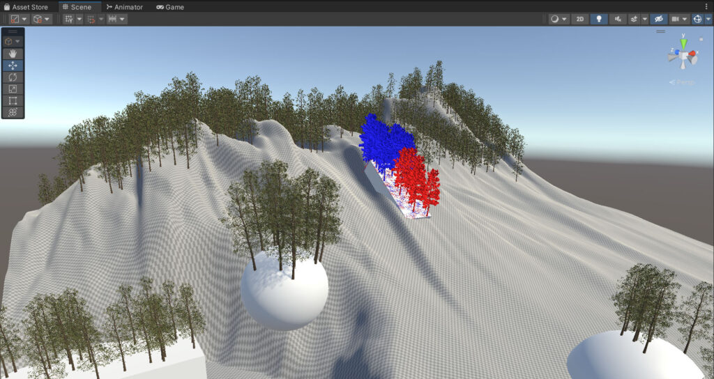
Take your Foliage Renderer workflow to the next level with the Mesh Providers Module! This Module allows you to paint, or procedurally place, Terrain Trees and Details on to Meshes for FR Rendering!
Getting Started
Be sure to check out this Walkthrough Video if you are just getting started with Foliage Renderer.
Limitations and Requirements
Foliage Render Mesh Module requires Foliage Renderer 2, but has no additional limitations or requirements outside of Foliage Renderer’s typical restrictions.
The Foliage Renderer requires Shaders that are compatible with its custom format. It can, however, patch many shaders automatically.
A Shader with support for all the shader features used by this package is included (wind, terrain aligned details, terrain albedo tinting, instancing), but if you need a more comprehensive Shader the Foliage Renderer Deluxe Shader contains support for all of these features as well. For high quality vegetation specific Shaders, we’d recommend the Vegetation Engine, which has full support for Foliage Renderer.
Foliage Renderer supports up to 4 LODs per object. CrossFade mode on LODGroups is supported – Speed Tree cross fade and animate crossfade are currently not supported. LODs must be uniformly scaled.
Foliage Renderer requires opaque or clipmap based Shaders, as it does not sort the resulting draw calls for alpha.
Technical Support
Technical Support is handled via the Dicewrench Designs’ discord group. Please read the documentation before seeking support, as many questions are already answered within.
High Level Concepts
If you are familiar with the High Level Concepts of Foliage Renderer 2 how the Mesh Module works will make a lot of sense.
Mesh Module adds a new set of Provider Components; MeshDetailProvider and MeshTreeProvider.
These Providers place Detail and Tree Prototypes through a series of procedural Filters or painted data to be rendered by the Indirect Renderer. Because they are Prototypes, they will of course be tracked and optionally overridden by the Indirect Draw Manager.
Setup
Setup Foliage Renderer in your scene if you haven’t already.
To add Trees and/or Details to Mesh Objects in your scene, do the following:
- Create an Empty GameObject
- Name it something useful like ‘MeshProvidersParent‘
- This is where we will add our Mesh Source and Provider Components
- Create or Parent any Mesh Renderers that you want to attach Trees or Details to.
- Parent these inside the MeshProvidersParent GameObject we made in Step 1.
- Select the MeshProvidersParent, use Add Component > Foliage Renderer > Providers and select Mesh Tree Provider or Mesh Detail Provider
- A Mesh Source component will also be added automatically.
- Now you can begin configuring and applying Trees and/or Details to your Meshes!
Working with Mesh Providers
Mesh Providers provide the ability to both; procedurally place Trees and Details, and/or paint Tree and Details. These two strategies work together to give you lots of control and good results very quickly.
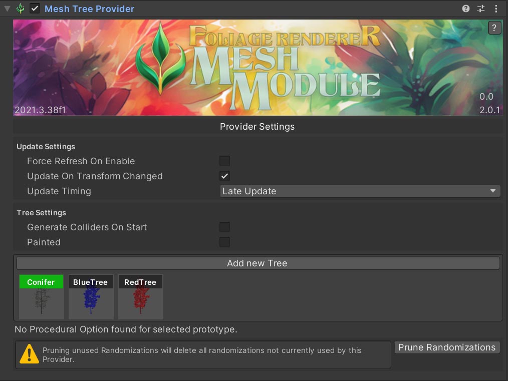
As with other Providers you have the typical Update Settings to setup as needed.
- Force Refresh On Enable
- Refresh this Provider’s Draws when it is Enabled.
- Update On Transform Changed
- Refresh this Provider’s Draws when the Transform of any of its Mesh Source Meshes change.
- Update Timing
- Set when in the update loop this Provider executes any needed Refresh.
There are some additional settings for Trees and Details base on the type of Provider.
- Tree Settings
- Generate Colliders On Start
- Creates Colliders for Trees on Refresh
- Painted
- Enables the ‘Start Painting’ button to launch the Vertex Painter and utilizes Painted Data for Tree Placement
- Generate Colliders On Start
- Detail Settings
- Aggressive Mesh Cell Pruning
- When enabled, Mesh Cell System Cells are pruned after the first Refresh. This can improve performance, but after drastic detail parameter changes Mesh Cells need to be rebuilt.
- Painted
- Enables the ‘Start Painting’ button to launch the Vertex Painter and utilizes Painted Data for Detail Placement
- Aggressive Mesh Cell Pruning
Selecting and Enabling Prototypes
An array of Prototype Icons will be displayed below the ‘Add New Tree/Detail’ Button. These Prototypes are pulled from the Indirect Draw Manager, so if you already have some Prototypes populating your Scene, you will be ready to add those same Trees and Details right onto your meshes!
If you need a new Tree/Detail not already in the scene, click the New button in the Inspector above the icons and populate the popup window.
By default, Prototypes are not enabled, you can click on them and toggle their labels to Green to enable them.
We will discuss updating Tree/Detail placement and settings in detail below.
Calibrating your Prototype Settings
Every enabled Prototype has some common settings:
| General Prototype Settings | |
| Seed The random value used to determine the noise for placing Prototypes | 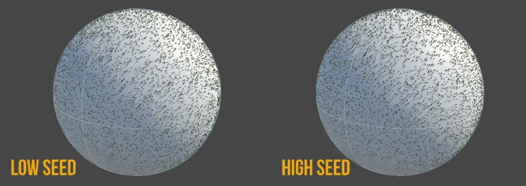 |
| Density How closely Prototypes should be placed to one another. The higher the value, the more close. | 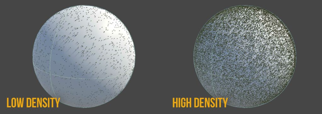 |
| Weight How many Prototypes should be placed. This appears much like changing Density, but doesn’t change how close together Prototypes can be placed. |
| Randomization Settings | |
| Slope Alignment How aligned to the Mesh’s Surface Normal should this Prototype be? A value of 0 will point straight up in world space. A value of 1 will point straight out, perpendicular to the Mesh’s Surface Tangent. | 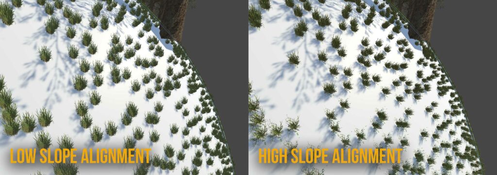 |
| Y Offset How much should this Prototype be nudged back into or out of the Mesh. Positive values go “down” into the Mesh. Negative values go “up” away from the Mesh. | 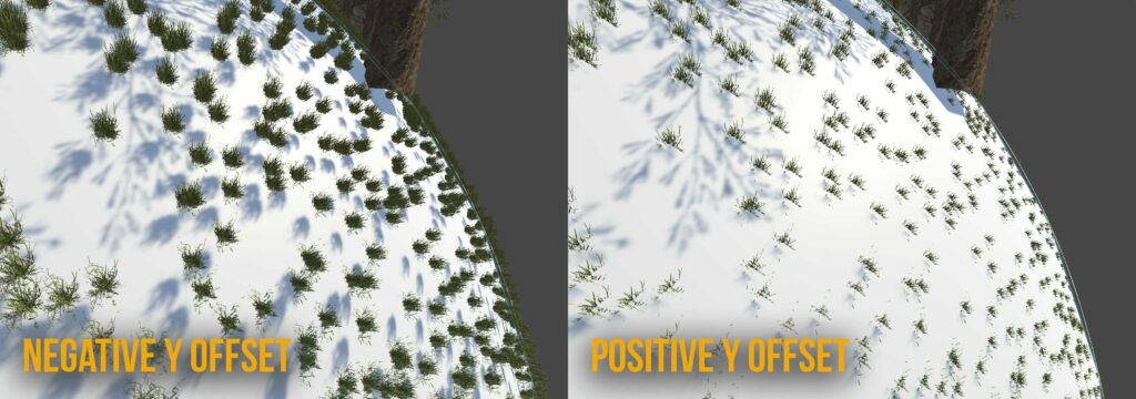 |
| Scale By Weight Multiplies a given Prototype Instance’s Scale by this number based on the procedural noise value at its given point in space. Useful to add some additional variety. | |
| Scale Lock Lets you choose to how to Scale Prototype Instances. The dropdown lets you choose which axis stay “locked” at Scale of 1. The “unlocked” axis you can define the range for. | None: All three axis, X, Y, Z, have their own min and max ranges you can set XY: X and Y locked, only Z changes. XZ: X and Z locked, only Y changes. YZ: Y and Z locked, only X changes XYZ : Uniform Scaling |
| Rotation Lock Similar to Scale Lock, this lets you choose what axis Prototypes should be randomly rotated along and to what amounts. | The options are the same as Scale Locking but modify Rotation, you get the idea… Typically you will want to lock XZ rotation and randomize Y. |
Beyond these common procedural settings there are additional Filter Settings you can apply to modify the placement of Prototypes. All Filters share some common Settings
| Enabled Toggle Should this Filter be enabled or not? |
| Weight How much should this Filter impact placement compared to other Filters? |
| Range Within what limits should this Filter be applied, varies by Type. |
| Smoothing What falloff in World Space Units should be applied at the edges of this Filter. |
| Height | |
| Limits Prototype placement to within a range of min and max World Space Y Position. | 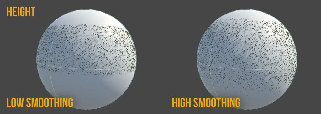 |
| Slope | |
| Limits Prototype placement to within a range of min and max Mesh Normal Angle relative to World Up Normal. | 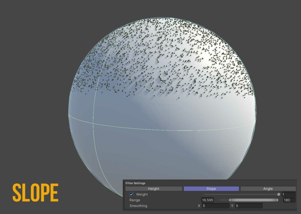 |
| Angle | |
| Limits Prototype placement to within a range of min and max Angle around the Mesh’s Y Axis. | 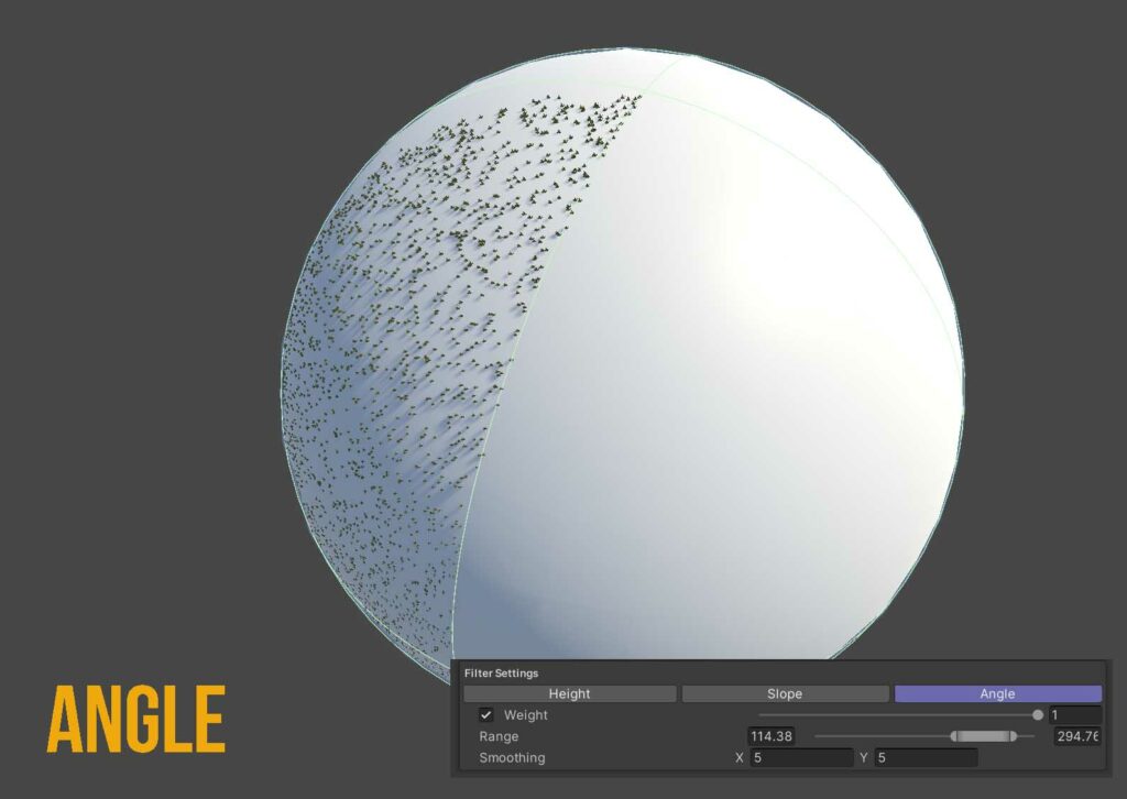 |
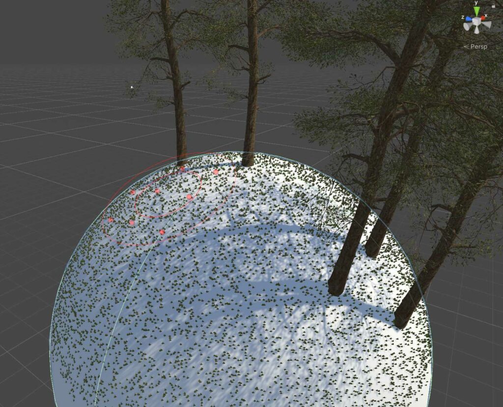
Painting Mesh Prototypes
If you would like to Hand Paint down Prototypes onto your Meshes you can use Painted Vertex information as an additional Filter.
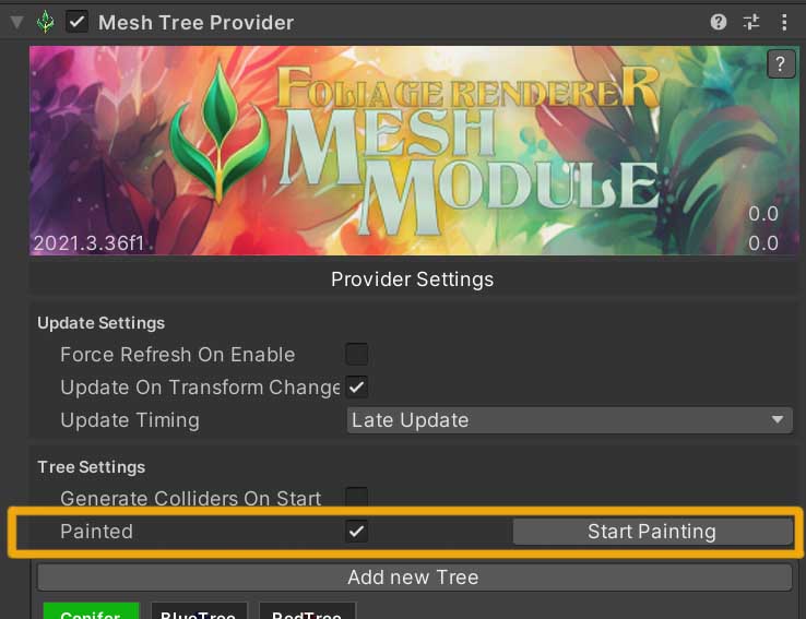
To do so, under Tree or Detail Settings in your Provider, check on the ‘Painted’ checkbox, this will expose a ‘Start Painting’ button. Click the ‘Start Painting’ button to open the Vertex Paint Editor Window.
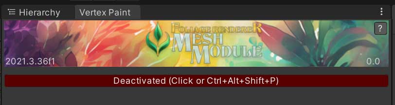
By default the Vertex Paint Editor Window will be Deactivated. This is so your Scene View inputs are not intercepted, and you can navigate as expected. When you are ready to start painting you can click the Red ‘Deactivated’ Button to toggle the Vertex Paint Editor Window on, or use Ctrl/Cmd + Alt + Shift + P to enable it.
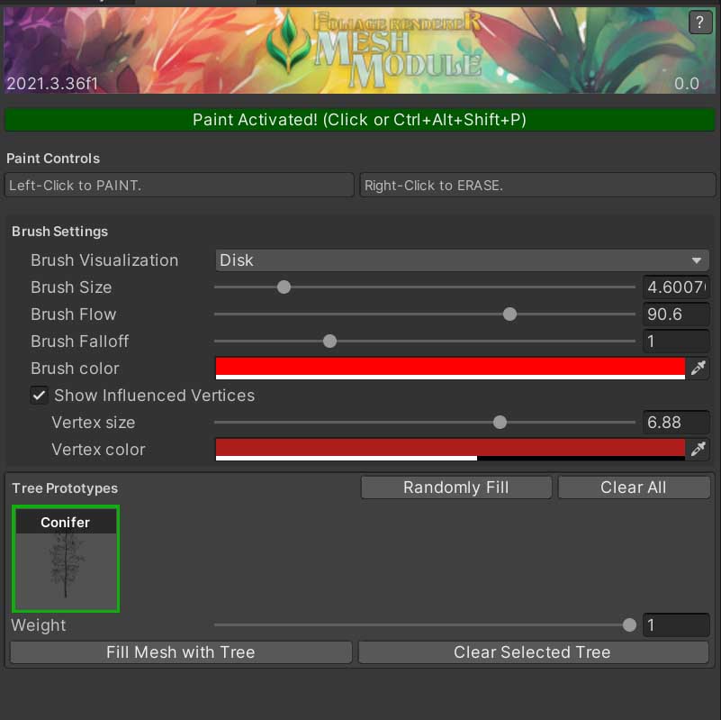
Left-Click to Paint. Right-Click to Erase.
There are a variety of Brush Settings you can adjust:
- Brush Visualization
- The shape of the Brush Gizmo in the Scene View; Disc or Sphere
- Brush Size
- The size of the Brush
- Brush Flow
- The rate at which Paint is applied to the Mesh while Left-Click is held down
- Brush Falloff
- The gradient falloff of Paint from the center of the Brush to the edges of the Brush. More paint will be applied at the Center, and less at the Edges.
- Brush Color
- The color of the Brush Gizmo in the Scene View
- Show Influenced Verts
- Enabling this checkbox will show a small Sphere Gizmo on each Vertex that will be modified by the next Brush Stroke
- Vertex Size
- The size of the Vertex Gizmo placed in the Scene View on an effected Vertex
- Vertex Color
- The color of the Vertex Gizmos
- Vertex Size
- Enabling this checkbox will show a small Sphere Gizmo on each Vertex that will be modified by the next Brush Stroke